

Description:-
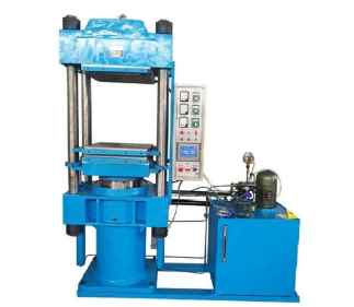
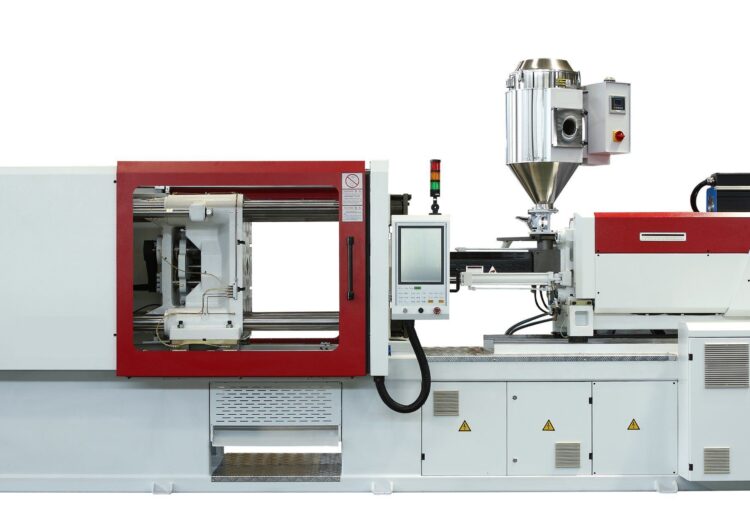
Injection moulding is the most common manufacturing process used to produce plastic parts. The process utilizes a machine, raw material, and a mould of the product part being produced to consistently manufacture high volumes of identical objects at a fast rate.
Machines are categorized and rated based on their clamping pressure or tonnage. The higher the clamping pressure, the larger the machine, and the larger the parts that it is able to fabricate. Clamping pressures vary anywhere from 5 tons to 6000 tons. The clamping pressure required to give optimum results for a product part is determined by the projected area of the part in the mould. Using clamping pressures that are too high or too low for a certain part can lead to defects such as flashing, where molten material seeps out of the mould and solidifies, leading to an unwanted thin layer of material forming around the part.
The raw materials used are chosen based on the function and specifications of the final product part. However, each material also has various parameters that need to be considered within the process. Most polymers can be used in the process, including all thermoplastics (nylon, polystyrene, polyethylene) and some thermosetting plastics (epoxy, phenolic). Though being mainly used for the production of plastics, other materials may also be used with injection moulding.
The main components of the process are described below:
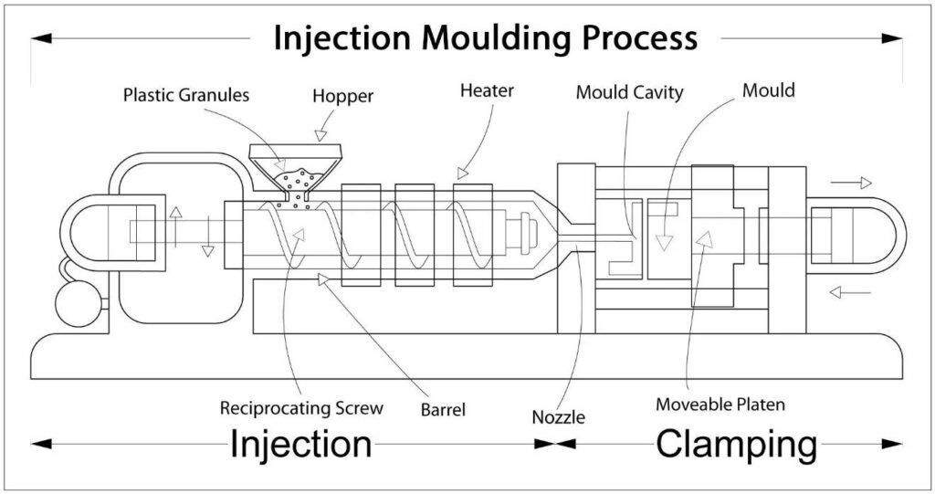
Injection Moulding Process
Moulding – A mould in the shape of the product part is designed using CAD, manufactured, and split into two halves.
Clamping – The two halves of the mould are pushed and held securely closed by the clamping unit of the machine. Larger machines will require a longer time than smaller machines to carry out this step.
Injecting – The raw materials, usually in the form of pellets, are melted by heat and pressure, then injected into the mould very quickly, filling the entire space within it. The build-up of pressure packs and holds the material together. The exact amount of material injected in the mould is referred to as the shot.
Cooling – The molten material within the mould begins to cool as it makes contact with the mould surfaces, solidifying into the shape of the desired part.
Ejecting – The clamping unit separates the two halves and the cooled, finished part is ejected from the mould via the ejection unit.
The production cycle is very short, usually lasting between 2 seconds and 2 minutes. Upon the completion of step 5, the cycle restarts at step 2, manufacturing a replica of the part.
| KMT Models | 100 T | 225 T | 500 T | 100 T | 225 T | 500 T | 100 T | 225 T | ||||||||||||||||||||||||||||||||||
| Injection Unit | UNIT | |||||||||||||||||||||||||||||||||||||||||
| Screw Type | A | B | C | A | B | C | A | B | C | A | B | C | A | B | C | A | B | C | A | B | C | A | B | C | ||||||||||||||||||
| Screw Diameter | mm | 35 | 40 | 45 | 35 | 40 | 45 | 40 | 45 | 50 | 45 | 50 | 55 | 55 | 60 | 65 | 65 | 70 | 75 | 70 | 75 | 80 | 75 | 80 | 85 | |||||||||||||||||
| Injection Capacity (PS) | gms | 149 | 195 | 240 | 149 | 195 | 240 | 231 | 305 | 377 | 370 | 457 | 553 | 576 | 685 | 804 | 1094 | 1269 | 1456 | 1343 | 1542 | 1755 | 1855 | 2060 | 2335 | |||||||||||||||||
| Injection Pressure | bar | 1950 | 1540 | 1180 | 2260 | 1730 | 1377 | 1950 | 1540 | 1180 | 1950 | 1540 | 1180 | 1950 | 1540 | 1180 | 2044 | 1885 | 1732 | 2224 | 2073 | 1911 | 1800 | 1580 | 1400 | |||||||||||||||||
| Injection Rate | cc/sec | 79 | 103 | 130 | 122 | 159 | 201 | 106 | 134 | 165 | 114 | 141 | 170 | 175 | 209 | 245 | 250 | 290 | 332 | 295 | 338 | 385 | 370 | 420 | 480 | |||||||||||||||||
| Screw Stroke | mm | 180 | 180 | 180 | 160 | 160 | 160 | 198 | 198 | 198 | 240 | 240 | 240 | 250 | 250 | 250 | 340 | 340 | 340 | 360 | 360 | 360 | 420 | 420 | 420 | |||||||||||||||||
| L/D Ratio | 23.5 | 20.5 | 18.3 | 21.9 | 19.2 | 17.1 | 22.5 | 20 | 18 | 23.3 | 21 | 19 | 23 | 21.1 | 19.5 | 23.1 | 21.5 | 20 | 23 | 21.5 | 20.1 | 21.9 | 20.5 | 19.3 | ||||||||||||||||||
| Screw Speed | RPM | 240 | 240 | 240 | 240 | 240 | 240 | 240 | 240 | 240 | 250 | 250 | 250 | 235 | 235 | 235 | 215 | 215 | 215 | 205 | 205 | 205 | 190 | 190 | 190 | |||||||||||||||||
| Plasticizing Rate | gm/sec | 14 | 17 | 23 | 14 | 17 | 23 | 15 | 24 | 34 | 30 | 36 | 46 | 44 | 50 | 58 | 60 | 64 | 68 | 69 | 79 | 88 | 79 | 89 | 100 | |||||||||||||||||
| Total Heating Capacity | kw | 6.5 | 10.2 | 25.5 | kw | 7.8 | 21.5 | Total Heating Capacity | 7.8 | |||||||||||||||||||||||||||||||||
| Clamp Unit | Clamp Unit | |||||||||||||||||||||||||||||||||||||||||
| Clamp Force | Ton | 80 | 160 | 400 | Ton | 125 | 320 | Clamp Force | 100 | |||||||||||||||||||||||||||||||||
| Clamp Stroke | mm | 330 | 435 | 730 | mm | 395 | 660 | Clamp Stroke | 360 | |||||||||||||||||||||||||||||||||
| Max Day Light | mm | 730 | 935 | 1480 | mm | 845 | 1320 | Max Day Light | 810 | |||||||||||||||||||||||||||||||||
| Minimum Mould Height | mm | 150 | 200 | 320 | mm | 180 | 300 | Minimum Mould Height | 145 | |||||||||||||||||||||||||||||||||
| Maximum Mould Height | mm | 400 | 500 | 750 | mm | 450 | 660 | Maximum Mould Height | 450 | |||||||||||||||||||||||||||||||||
| Platen Size (H x V) | mm | 625 X 625 | 715 X 715 | 1130 X 1130 | mm | 660 X 660 | 970 X 970 | Platen Size (H x V) | 600 X 600 | |||||||||||||||||||||||||||||||||
| Tie Bar Distance | mm | 370 X 370 | 485 X 485 | 760 X 760 | mm | 430 X 430 | 660 X 660 | Tie Bar Distance | 400 X 400 | |||||||||||||||||||||||||||||||||
| Tie Bar Diameter | mm | 65 | 85 | 130 | mm | 75 | 115 | Tie Bar Diameter | 70 | |||||||||||||||||||||||||||||||||
| Locating Ring | mm | 100 | 125 | 160 | mm | 125 | 160 | Locating Ring | 125 | |||||||||||||||||||||||||||||||||
| Ejector Stroke | mm | 110 | 170 | 200 | mm | 150 | 180 | Ejector Stroke | 120 | |||||||||||||||||||||||||||||||||
| Ejector Force | kN | 36 | 61.5 | 102 | kN | 45 | 80 | Ejector Force | 42 | |||||||||||||||||||||||||||||||||
| General | General | |||||||||||||||||||||||||||||||||||||||||
| Total Connected Load | kw | 15.5 | 25.2 | 52.5 | kw | 18.8 | 45.5 | Total Connected Load | - | |||||||||||||||||||||||||||||||||
| Servo Motor | kw | 09 | 15 | 27 | kw | 11 | 24 | Servo Motor | 15 | |||||||||||||||||||||||||||||||||
| Oil Capacity | liter | 210 | 250 | 450 | liter | 210 | 415 | Oil Capacity | 200 | |||||||||||||||||||||||||||||||||
| Machine Diamension (L x W x H) | meter | 4.5 X 1.2 X 1.6 | 5 X 1.2 X 1.8 | 8 X 1.75 X 2.4 | meter | 4.76 X 1.2 X 1.7 | 7 X 1.65 X 2.2 | Machine Diamension (L x W x H) | 4.1 X 4.1 X 1.8 | |||||||||||||||||||||||||||||||||
| Machine Weight | tons | 3.8 | 4.8 | 14.7 | tons | 4 | 11 | Machine Weight | 3.6 | |||||||||||||||||||||||||||||||||
| Water Requirment | lpm | 65 | 85 | 120 | lpm | 85 | 100 | Water Requirment | 65 | |||||||||||||||||||||||||||||||||